Accurate Miniatures 1:48 A-36 Apache
|
Larry Z. Daily’s Personal Page Accurate Miniatures 1:48 A-36 Apache |
| This project is actually the first in a series:
I want to build — in 1:48 scale — an example of each variant of the P-51 Mustang flown by the US in World War II. I decided to start with the A-36. The A-36 was a
dive-bomber version of the Mustang. In spring of 1942, there was interest in the U.S. Army Air Corp in obtaining Mustangs,
but the budget for pursuit aircraft (fighters) was exhausted. There was, however, money available for attack aircraft (which
included dive-bombers). North American was asked to develop a dive-bomber variant of the Mustang and an order was placed for
500 of the new plane, designated the A-36, in April of 1941. The A-36 entered service in 1942 and was retired in 1945.
I have to be honest here: this is actually the second AM A-36 that I’ve built. I built the first one pretty much straight out of the box (which bothered me) and I used the kit decals. The build actually went fairly well, but I had difficulty fitting the canopy and I didn’t weather it at all. When I realized that the markings represented an aircraft that had been in service quite some time (and thus had what I now know to be mission markings stretching from one end of the plane to the other), the factory-fresh finish really began to bug me. I just had to build another one. So, I hit eBay and grabbed another kit. I also had noticed in my research that pretty much every built-up A-36 that I saw online used the kit decals. I wanted something different, so I went looking for replacement decals. The ones I found were for Pat, the aircraft flown by Lt. Michael Russo. Russo was assigned to the 382nd Fighter Bomber Squadron, 27th Fighter Bomber Group, in the Twelth Air Force in the Mediterranean Theater of Operations (MTO). Russo is noteworthy as the only pilot to attain ace status flying the A-36. Prototype: Model: A-36 Serial number: 42-83830 Nickname: Pat Pilot: Michael T. Russo Kit: Accurate Miniatures 1:48 A-36 Apache In addition to the kit, I obtained a bunch of aftermarket parts:
|
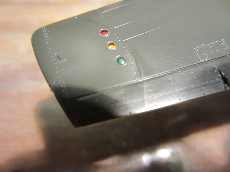 |
(1) The first thing I did was to open up the formation lights using a 1/16" drill bit. I polished one end
of three pieces of 1/16 clear styrene rod and glued them into the holes with the polished ends flush with the outer surface
of the wing. After letting the joints dry for over 24 hours, I cut the rods off flush with the inside of the wing and polished
the surfaces. Then I used Tamiya clear red, yellow, and green to color the lights. The sources that I have indicated that the
color of the lights was — from front to back — red, yellow, and green. Since I finished this build, I’ve found
a number of sites online that say that the Mustang formation lights were — again, front to back — red, green, and yellow.
I don’t know whether the order of the colors differed across different types of planes, but on page 27 of Kinzey’s
Detail & Scale book on the early Mustangs is a photo of the wing of an A-36. The caption says that the lights are red, yellow,
and green and the photo seems to support that. In addition, there are color photos on pages 91 and 94 of Skulski’s book on
the A-36 that show the middle and rear lights. The middle one is clearly yellow and the rear one green. So, I’m not going to sweat the
colors I used. |
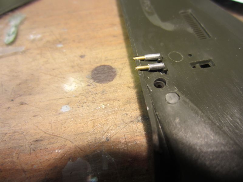 |
(2) While I was working on the wings, I replaced the kit gun barrels with
replacements made from nested tubing. |
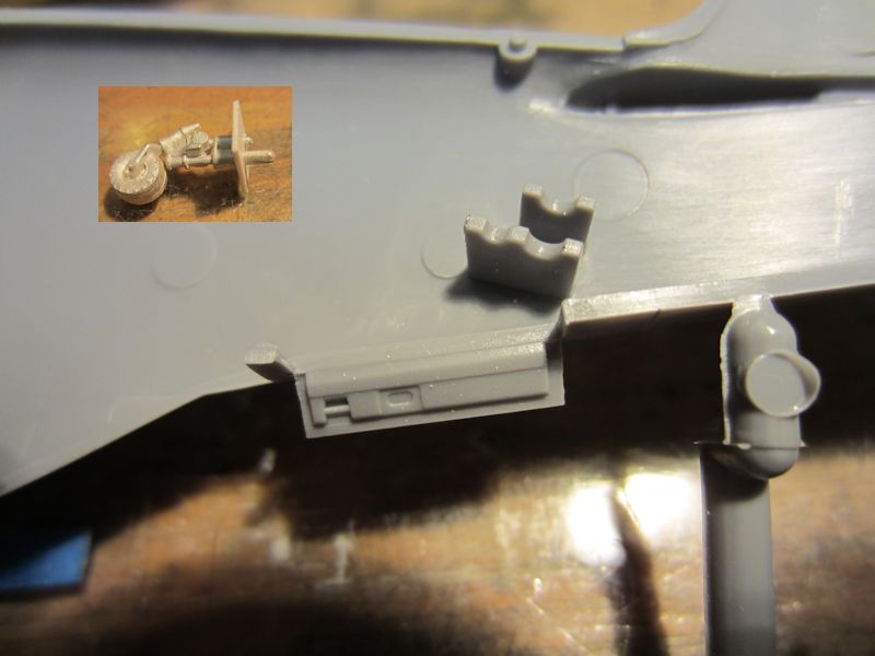 |
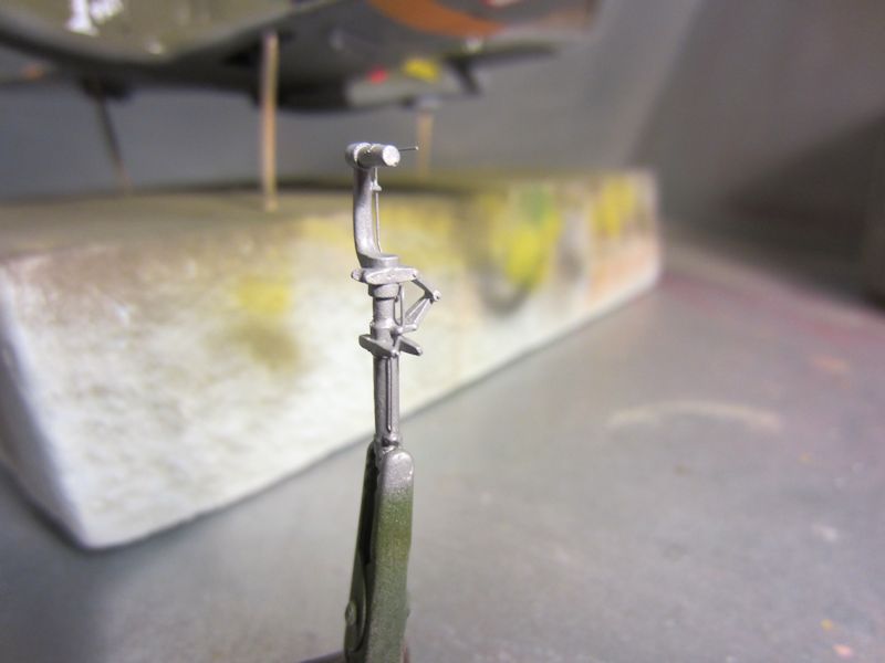
(3) I wanted to use the Scale Aircraft Conversions tail wheel. The SAC set is intended for the Tamiya kit, which has
a much more secure means of attaching the tail wheel. This photo shows the Tamiya attachment point with the SAC white metal tail wheel
in the inset. The tail wheel has been inserted into part of my replacement mount. |
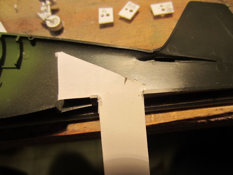 |
(4) I have a lot of leftover business cards, so they get pressed into all kinds of service on my workbench.
Here, I’ve cut one into a template so that I can glue my tail wheel mount in at the same angle as the Tamiya kit. |
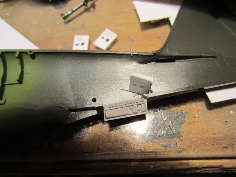 |
(5) Here’s the new mount in the fuselage. The bottom piece (the one most visible in the photo) is made
from sheet styrene. The corresponding part in the Tamiya kit was .035" thick, so I made mine by laminating .030 and .005
styrene. It’s .22" front-to-back and .349" side-to-side (at the front of the piece), with a slight taper toward the rear
to match the contour of the fuselage. The forward hole is #57 (.043") and the rear one is #53 (.059), spaced to accept the
SAC part. The top piece is made from .030 styrene with a single #57 hole. I didn’t think the width of the top piece
was critical, so I left about .06" on either side of the hole. I attached the top part to the bottom using .040x.040 strip
as spacers. After the whole assembly dried, I added it to the fuselage. |
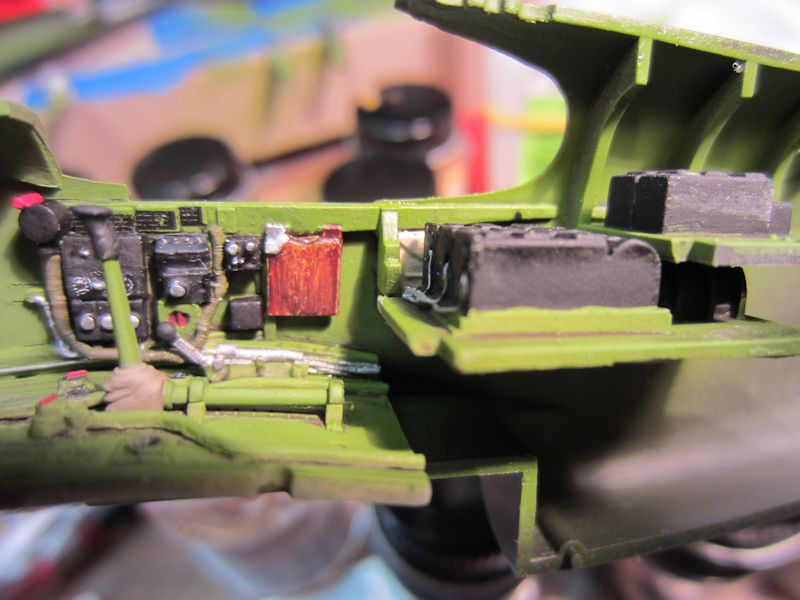 |
(6) Here’s the starboard side of the fuselage with its mix of True Detail and kit
parts. There’s a lot to like about the True Details parts, but there are some things I don’t
like as well. Among those are that some parts that should be knobs (such a the red bit in the photo)
are cylinders and a lot of bits that look like flat guages or dials in the photos are also cylindrical. |
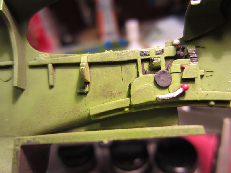 |
(7) Here’s the port side. The main color is Model Masters Interior Green, with details
picked out in black or red. The weathering is a burnt umber wash. |
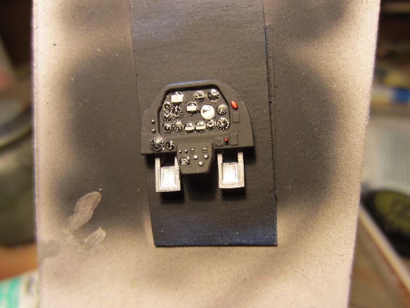 |
(8) I ended up having to use the kit instrument panel. The True Details molds apparently
didn’t fill completely in my kit and the part was missing one rudder pedal and most of the instrument panel
between the pedals. I cut apart the AM instrument panel decal and applied the dials individually to the front of the
panel. Once they’d dried, I put a dot of Micro Kristal Klear on each one to simulate glass. |
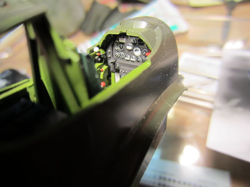 |
(9) Here’s the instrument panel in place. I think it looks pretty good. Once
the canopy is in place it will be hard to see clearly. Note the red bit on the right of the
cockpit. As noted above, it’s supposed to be a knob. In this photo it’s really clear
that it isn’t. |
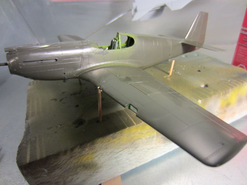 |
(10) Off to the spray booth for some paint! Note that I filled in the huge hole in the port
wing to provide a mounting for MV Products lenses to represent the landing lights. I’ve also added
the seat. I ended up trying three times or more to get the seat in properly; for some reason that I never
quite figured out it would settle in twisted slightly — but noticeably — toward the starboard side of the
cockpit. |
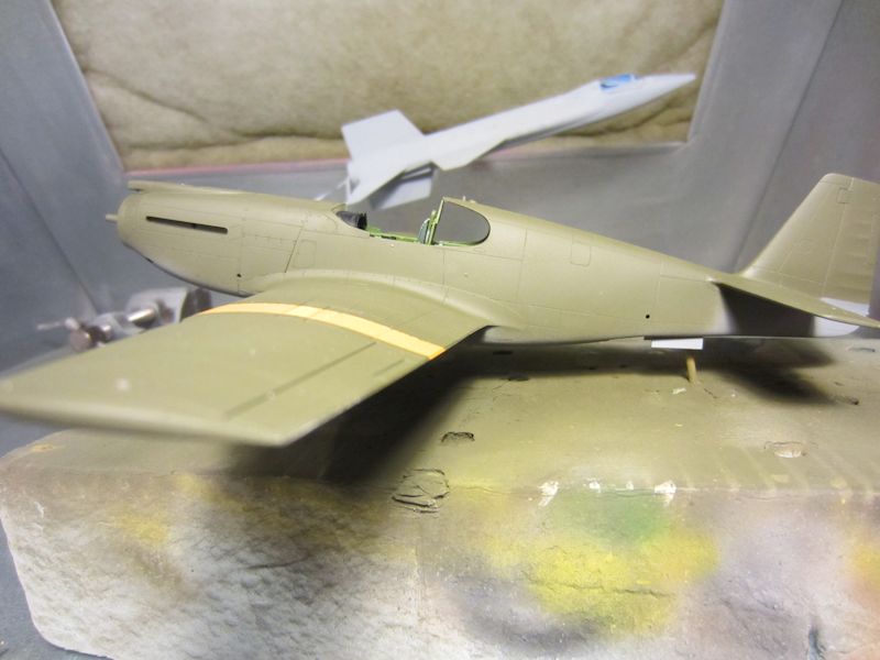 |
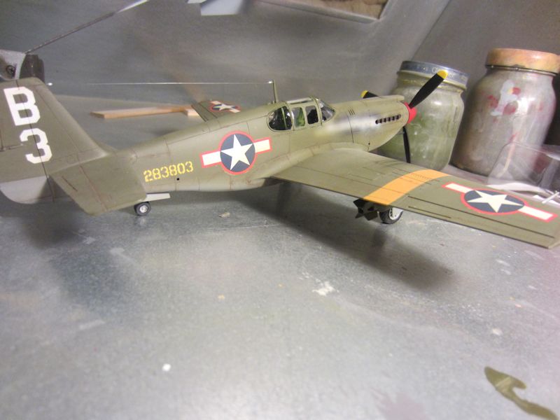
(11) I started by spraying the area where the yellow ID stripes would be. I filled the color cup
on my airbrush most of the way with Model Masters Insignia Yellow and then added a couple of drops of MM Insignia Red.
Once that dried, I masked the stripes and sprayed the bottom with MM Neutral Gray and the top with MM Olive Drab. |
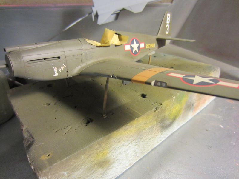 |
(12) The SuperScale Decals set included markings for the aircraft flown by Lt. Michael Russo, the
only A-36 ace. In my search of the Internet for information on the A-36 I didn’t find another model of Russo’s
plane, so I decided to model it. In this shot, the decals are on and I’ve added a bit of weathering. I made a wash of
burnt umber oil paint and Turpenoid and flowed that into the panel lines. Then I used a light overspray of Model Masters
Afrika Khakibraun to give the plane an overall dingy, well-used look. Then I needed to stop and try and figure out the best way
to represent the distinctive exhaust stains that were common on the Allison-engined Mustangs. |
 |
(13) While I was working on that problem, I turned my attention to the landing gear struts. I wanted to add the
brake lines. I made brackets for the lines using .010x.040 styrene strip. I drilled a #80 hole close to one end of the strip.
Then I used a sanding stick to bring the size down to just a hair bigger than the hole I just drilled. Finally, I used a fresh
single-edged razor blade to remove the bracket from the strip. I made four for each strut, two for the part of the brake line
from the top of the strut to just above the oleo and two for the line below the oleo. The brake line above and below the oleo was
formed of .008 brass wire. The part connecting them — meant to represent flexible rubber tubing — was formed of .012
brass wire. |
 |
(14) I’ve made a bit of progress. The exhaust staining took me several tries and I’m still
not sure that I like it. The main color is Model Masters Sand with some Neutral Gray added. The soot is black
chalk. The exhaust stacks were first sprayed with Testor’s Burnt Metal Metalizer paint.
After that dried, I dipped them into some Rust-all solution several times. Finally, I brushed on a bit of black
chalk powder. |
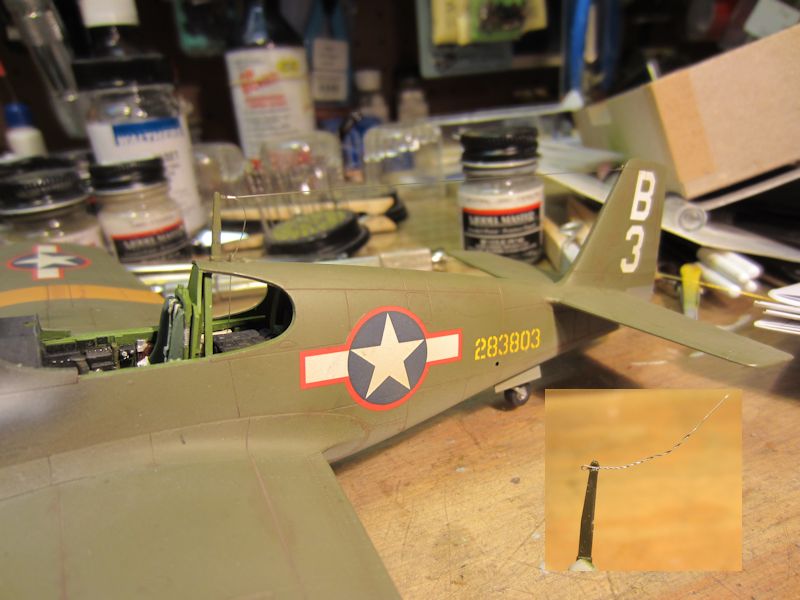 |
(15) This project marks my first attempt to model the antenna wire on a Mustang. I thought
long and hard about how to attempt it. I also searched the Net repeatedly. The most popular method seems
to be stretched sprue. I’m not sure that I could pull that off. I finally settled on a modification
of a method that I learned for rigging WWI biplanes. First, I made two small eyelets by wrapping a single
strand of very fine wire around a piece of .010 brass wire and twisting the ends. Then I drilled a #80
hole in the vertical stabilizer and mounted one of the eyelets in it with ACC. Then, using the edge of a
triangular needle file I created a groove near the top of the antenna mast. I glued the second eyelet
in the groove (see the inset in the photo). When that dried, I trimmed it to length, puttied over it, and
sanded everything smooth. I represented the insulators with .5 mm brass tubing. The antenna wire itself is "invisible"
thread. I ran one end through an insulator, then through the eyelet on the vertical stabilizer, and then back through
the insulator. I snugged everything up against the tail eyelet and touched a drop of ACC to the insulator to fix everything
in place. I repeated the process at the antenna mast, but then threaded the loose end through a hole in the fuselage. |
 |
(16) In this photo, I’ve added the canopy. I'm not really crazy about the fit of the Accurate Miniatures
canopies. This is ok, but close examination reveals gaps that I just couldn’t avoid. This photo also shows my
second attempt at the antenna. I had to salvage the antenna mast off the old kit to replace the one that snapped off
when my finger caught the antenna wire while I was adding the landing light clear part. Important lesson: add the antenna
wire last. All that’s left at this point is to paint the nav lights and add the bombs. |
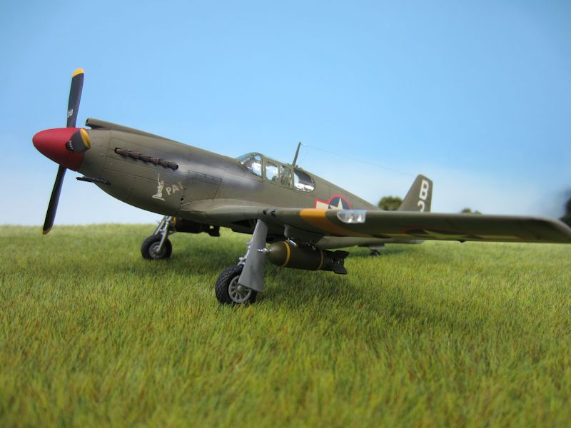 |
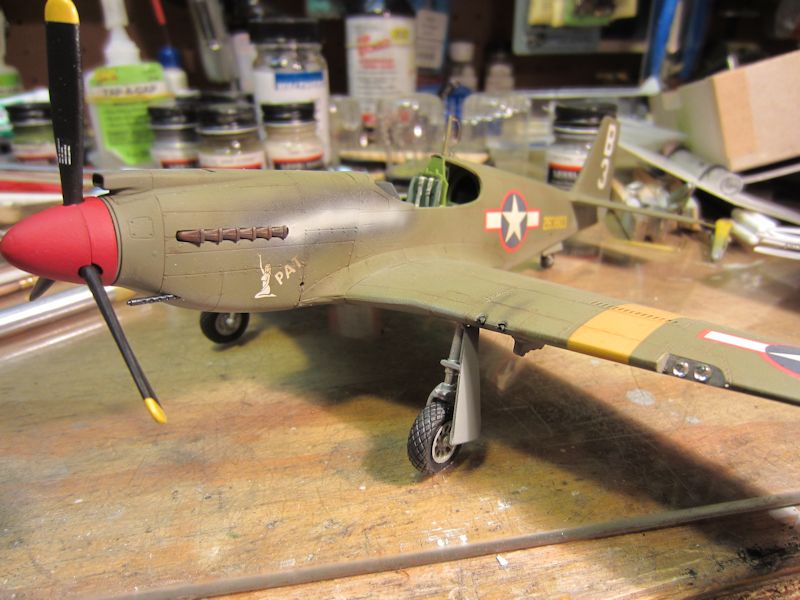
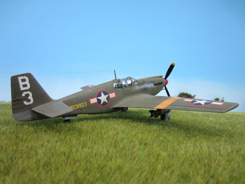
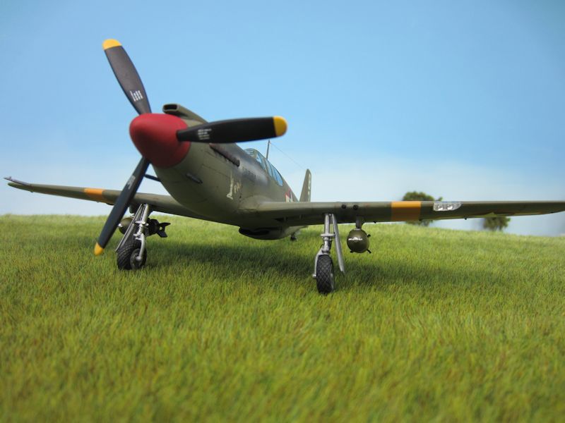
(17) Finally done! I had more trouble than I care to admit with the bombs (I guess you could
say that I kept bombing). I tried to use yellow decal stripes to dress them up a bit, but they wouldn’t
lie down flat. I finally painted the bombs yellow, masked the stripes and then painted the rest olive
drab. I also feel somewhat compelled to admit that the antenna in these photos is my third
attempt. When I came down to my shop the morning after I took the previous photo, the mast had developed
a decided lean toward the rear of the plane. Before I replaced the mast with one scavenged from another
kit, I painted the nav lights chrome silver. When they were dry, I used Tamiya transparent red and green
on the starboard and port wing lights. For the tail light, I cut off the kit’s “lens.” and
then painted the resulting flat surface chrome silver. After that dried, I added a drop of Micro Krystal Kleer
to represent the lens. |
 |
(18) |
 |
(19) |
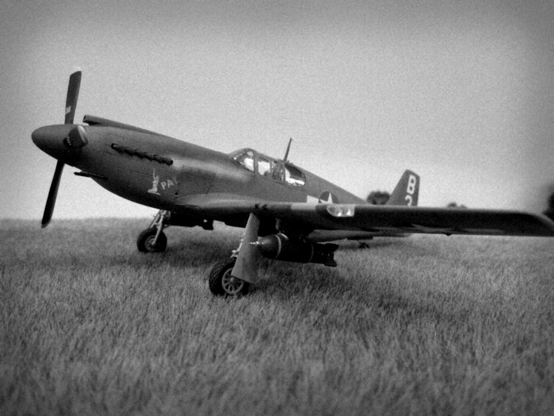 |
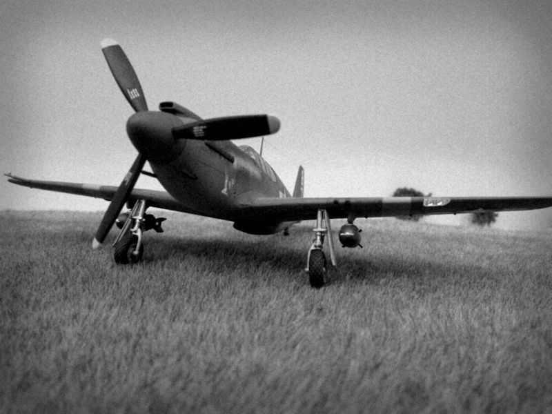
(20) Just for fun, I tried to replicate the look of black-and-white photos
taken with a box camera. I think they came out fairly nice. |
 |
(21) |
|
[home]
[trek]
[space]
[camel]
[p-51]
[vega]
[C&O]
[professional]
|